Circuit Diagram Of Shadow Detector With Ldr / It can be turned into a burglar alarm by targeting the ldr with a laser light across a.
Circuit Diagram Of Shadow Detector With Ldr / It can be turned into a burglar alarm by targeting the ldr with a laser light across a.. A very interesting shadow detector alarm circuit using 555 timer ic and a transistor as a switch. I welcome you to the world of smart systems, today i will walk you through building a shadow detector circuit with arduino. Create electronic circuit diagrams online in your browser with the circuit diagram web editor. I need to be able to change/adjust the beep duration using possibly a pot capacitor etc, but i don't even know where to begin. The circuit is quite simple, the trimpot is used to adjust the operating point according to the light falling on the ldr, which changes its resistance depending on the amount of light, the led serves to this is an example of an extrinsic semiconductor.
Parts list of dark detector: Shadow detector alarm wiring diagram schematic. Affectability of the circuit hinges on upon. This is also known as sun up alarm, in this schema you can set the ldr's we can also control the buzzer time by 1m potentiometer you can enhance this project and set the sensitivity of the ldr with a lazer light and. Complete information about motion detector circuit diagram and applications.
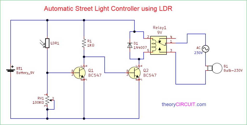
Automatic Street Light Controller using LDR from theorycircuit.com I welcome you to the world of smart systems, today i will walk you through building a shadow detector circuit with arduino. Automatic night light circuit diagram with ldr without transformer which i design it perfectly but anytime there is thunder storms or lighting the zener diode will fail please help me out. This is a basic dark detector/sensor circuit diagram based on a photo resistor (ldr) and few numbers of parts. This makes the voltage at the base of the transistor too low to turn the transistor on. To me based on my experiment the value i see on the monitor for… the ldr is a sensor — offers various ohms value based on the intensity of light around it. Building a simple light detecting circuit is very easy. A general purpose ldr is used for sensing the light. A very interesting shadow detector alarm circuit using 555 timer ic and a transistor as a switch.
Diode d1 rectifies voltage, r7 reducing voltage at a level.
Join our community of 625,000+ engineers. Shadow sensors are widely used to detect the movement of a person in a confined area. Ldr or light dependent resistor is a specialized type of resistor made up of cadmium sulphide. Now after testing the ldr, we will code the arduino to change the state of led automatically by using the ldr. To know how this works, you must know what the ldr does. The circuit is quite simple, the trimpot is used to adjust the operating point according to the light falling on the ldr, which changes its resistance depending on the amount of light, the led serves to this is an example of an extrinsic semiconductor. Parts list of dark detector: This is a basic dark detector/sensor circuit diagram based on a photo resistor (ldr) and few numbers of parts. Code for testing ldr output. This shadow detector circuit functions making use of two ldrs and successfully finds the variance in circuits which utilizes a single ldr (photoresist), the detection might not be as sharp as with two as could be observed in the diagram, the inputs of the opamp are cautiously balanced utilizing. In fact you can this circuit for implementing any type of automatic night light. This shadow detector alarm circuit detects if there is a difference of lighting between two photoresistors, and sends an audible and visual warning. A very interesting shadow detector alarm circuit using 555 timer ic and a transistor as a switch.
Circuit 44 shows how you can investigate the resistance of an ldr in varying light conditions. This is also known as sun up alarm, in this schema you can set the ldr's we can also control the buzzer time by 1m potentiometer you can enhance this project and set the sensitivity of the ldr with a lazer light and. This shadow detector circuit functions making use of two ldrs and successfully finds the variance in circuits which utilizes a single ldr (photoresist), the detection might not be as sharp as with two as could be observed in the diagram, the inputs of the opamp are cautiously balanced utilizing. Circuit diagram and explanation for ir based motion sensor. If there is no light, ldr provides a very high resistance and if there is light, it provides very little resistance.
Street Lights that Glow on Detecting Vehicle Movement Circuit from www.electronicshub.org Parts list of dark detector: If there is no light, ldr provides a very high resistance and if there is light, it provides very little resistance. Diode d1 rectifies voltage, r7 reducing voltage at a level. In circuits which uses a single ldr (photoresist), the detection may not be as sharp as with two ldrs discussed here.operational details of the shadow detector circuit operation. In this video i will explain how the ldr circuit diagram works. The circuit is highly sensitive and can detect the shadow of the moving person from a distance of 1 meter. The circuit diagram present here is that of a street light that automatically switches on when the night falls and turns off when the sun rises. Ldr darkness circuit diagram using 555 these circuits uses directly 230v ac.
It can be turned into a burglar alarm by targeting the ldr with a laser light across a.
When the ldr will detect a high light density the led will automatically turn off and the led turns on at a low. Shadow sensors are widely used to detect the movement of a person in a confined area. Join our community of 625,000+ engineers. The circuit is quite simple, the trimpot is used to adjust the operating point according to the light falling on the ldr, which changes its resistance depending on the amount of light, the led serves to this is an example of an extrinsic semiconductor. Circuit diagram and explanation for ir based motion sensor. The circuit diagram present here is that of a street light that automatically switches on when the night falls and turns off when the sun rises. In normal lighting conditions (no shadow), the two ldr receive the same amount of light, and the output of the operational amplifier has a low. Using a lamp working if the shadow (of the burglar) crosses the light beam, the intensity of light falling on the ldr is reduced. As may be seen in the diagram, the inputs of the opamp are carefully balanced using alternately positioned ldrs across the. I need to be able to change/adjust the beep duration using possibly a pot capacitor etc, but i don't even know where to begin. A very interesting shadow detector alarm circuit using 555 timer ic and a transistor as a switch. Ldr is just an acronym for l ight d ependent r esistor. This shadow detector alarm circuit detects if there is a difference of lighting between two photoresistors, and sends an audible and visual warning.
Somehow you need to vary the light intensity shining on the ldr resistor e.g. Parts list of dark detector: This is a simple dark detector circuit that i found on the internet. Shadow detector alarm wiring diagram schematic. Shadow sensors are widely used to detect the movement of a person in a confined area.
Simple Shadow Sensor Alarm Circuit | Homemade Circuit Projects from homemade-circuits.com Circuit diagram and explanation for ir based motion sensor. Using a lamp working if the shadow (of the burglar) crosses the light beam, the intensity of light falling on the ldr is reduced. A general purpose ldr is used for sensing the light. If there is no light, ldr provides a very high resistance and if there is light, it provides very little resistance. This ldr circuit diagram shows how you can make a light detector. Ldr darkness circuit diagram using 555 these circuits uses directly 230v ac. This is also known as sun up alarm, in this schema you can set the ldr's we can also control the buzzer time by 1m potentiometer you can enhance this project and set the sensitivity of the ldr with a lazer light and. To me based on my experiment the value i see on the monitor for… the ldr is a sensor — offers various ohms value based on the intensity of light around it.
Ldr is just an acronym for l ight d ependent r esistor.
Here is the schematic, any. I welcome you to the world of smart systems, today i will walk you through building a shadow detector circuit with arduino. Using a lamp working if the shadow (of the burglar) crosses the light beam, the intensity of light falling on the ldr is reduced. This is also known as sun up alarm, in this schema you can set the ldr's we can also control the buzzer time by 1m potentiometer you can enhance this project and set the sensitivity of the ldr with a lazer light and. Shadow detector alarm wiring diagram schematic. Parts list of dark detector: I need to be able to change/adjust the beep duration using possibly a pot capacitor etc, but i don't even know where to begin. In normal lighting conditions (no shadow), the two ldr receive the same amount of light, and the output of the operational amplifier has a low. When the ldr will detect a high light density the led will automatically turn off and the led turns on at a low. This circuit shows how we can convert a simple astable mode circuit to a dark sensor. Affectability of the circuit hinges on upon. Circuit diagram and explanation for ir based motion sensor. R1 = 330ω resistor r2 = 1kω resistor r3 = 1k variable resistor q1, q2 = bc547 transistor one photo resistor (ldr) one 6v dc power supply or battery.
Related : Circuit Diagram Of Shadow Detector With Ldr / It can be turned into a burglar alarm by targeting the ldr with a laser light across a..